
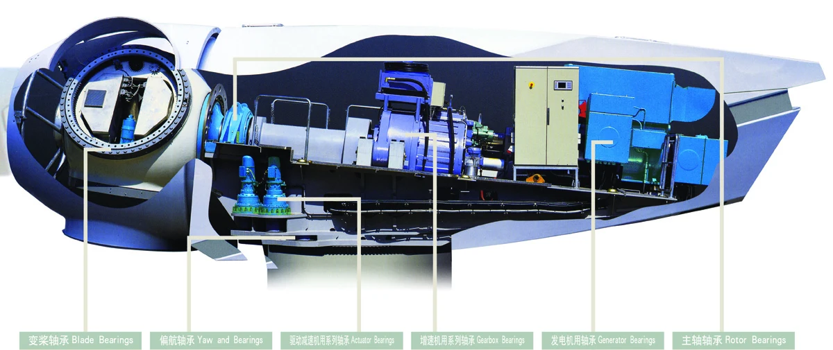
English guide to common diagram labels
The equipment descriptions explain these original diagrams in English. The original artwork is retained.
- 轴承
- Bearing
- 内圈
- Inner ring
- 外圈
- Outer ring
- 滚动体
- Rolling element
- 保持架
- Cage
- 密封
- Seal
- 径向
- Radial
- 轴向
- Axial
- 主轴
- Main shaft / spindle
- 偏航
- Yaw
- 变桨
- Pitch
- 齿轮箱
- Gearbox
- 发电机
- Generator
- 丝杠
- Screw
- 工作台
- Table
- 减速机
- Reducer
- 连铸
- Continuous casting
- 热轧
- Hot rolling
- 冷轧
- Cold rolling
- 烘缸
- Drying cylinder
- 压榨
- Pressing
- 破碎机
- Crusher
- 振动筛
- Vibrating screen
- 回转支承
- Slewing bearing
- 磨煤机
- Coal pulverizer
Yaw: nacelle orientation
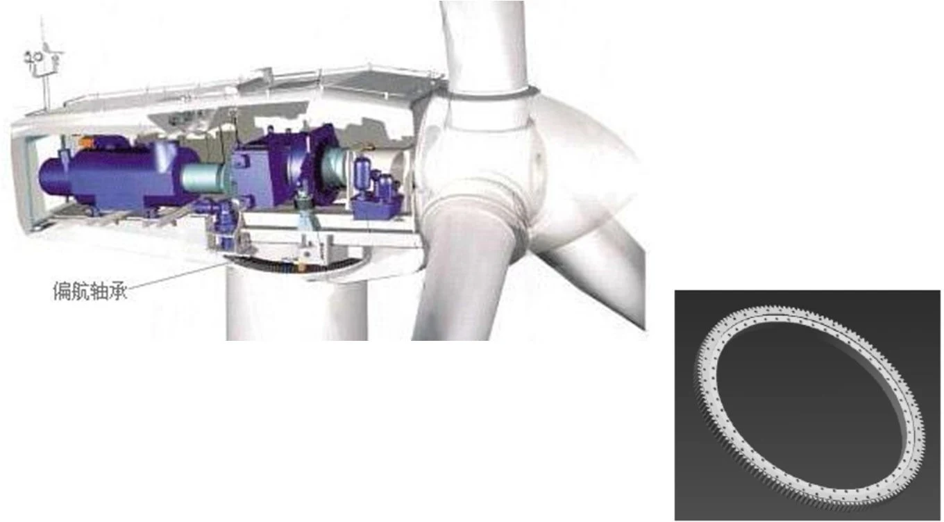
Bearing position
the tower-to-nacelle slewing support for yaw motion.
Conditions
slow rotation or oscillation with axial/radial loads, overturning moments and shocks; the presentation shows horizontal installation and grease lubrication.
Arrangement
single- or double-row four-point-contact ball slewing bearings with the appropriate gear/drive layout.
Engineering focus
assess the mounting interface, bolted joint, load distribution, seals and lubrication coverage together.
Pitch: blade-angle control
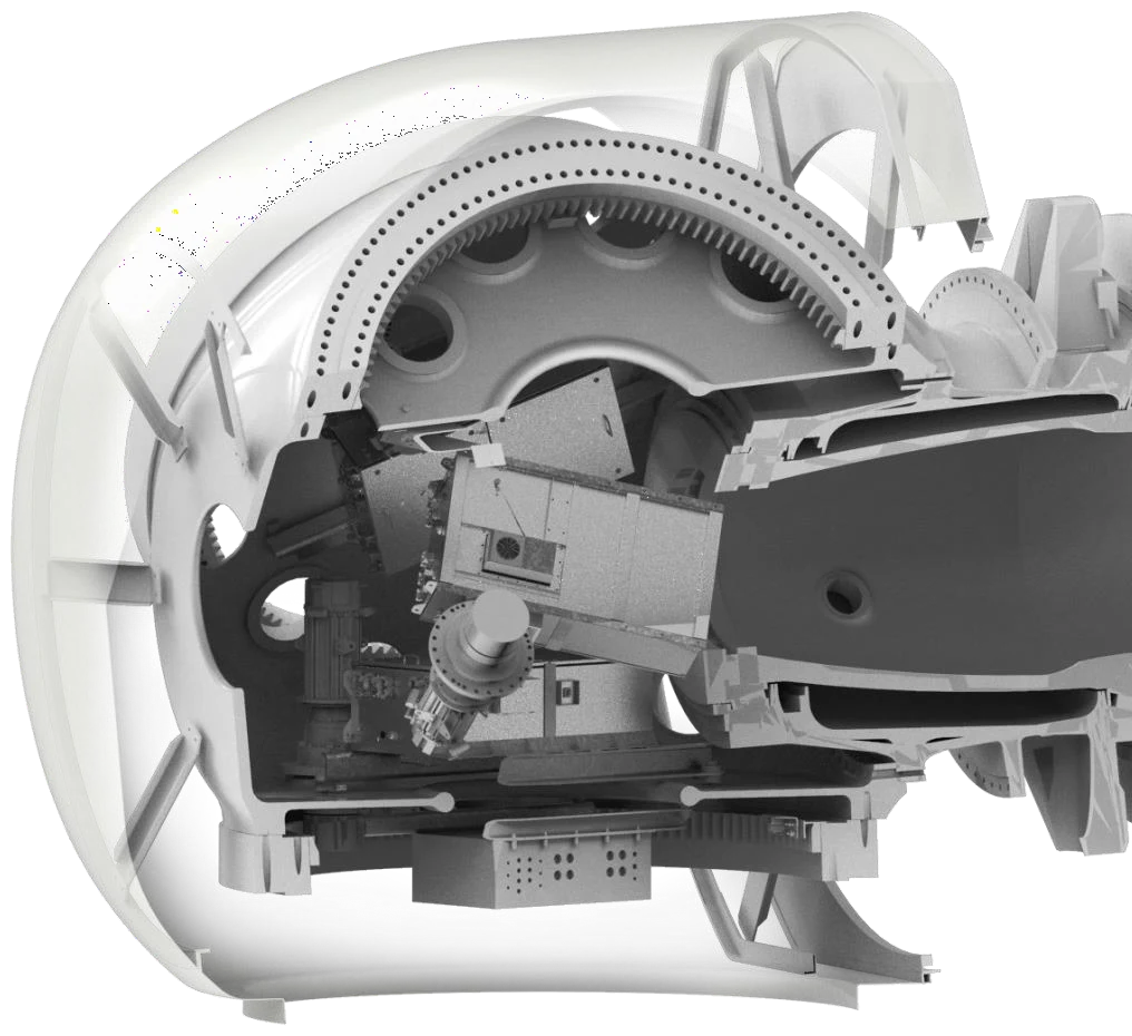
Bearing position
blade-root connection to the hub, working with the pitch drive.
Conditions
small-angle oscillation, changing loads and overturning moments, with a different orientation and loaded zone from yaw supports.
Arrangement
four-point-contact ball and three-row cylindrical-roller alternatives in the presentation.
Engineering focus
evaluate blade loads, hub stiffness, drive interfaces and lubrication access; yaw and pitch designations are not interchangeable.
DFIG main shaft: locating and floating supports
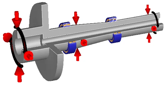
Bearing position
the main-shaft support connecting the rotor to the drive train.
Conditions
low-speed, grease-lubricated examples; load variation and shaft deflection affect roller contact.
Arrangement
CB-type spherical rollers at the locating side and CA-type at the floating side, with paired tapered-roller alternatives.
Engineering focus
split cages, roller-speed compensation, profiles and lubrication openings; investigate micropitting, wear and rib damage with operating evidence.
Semi-direct and direct-drive main shafts
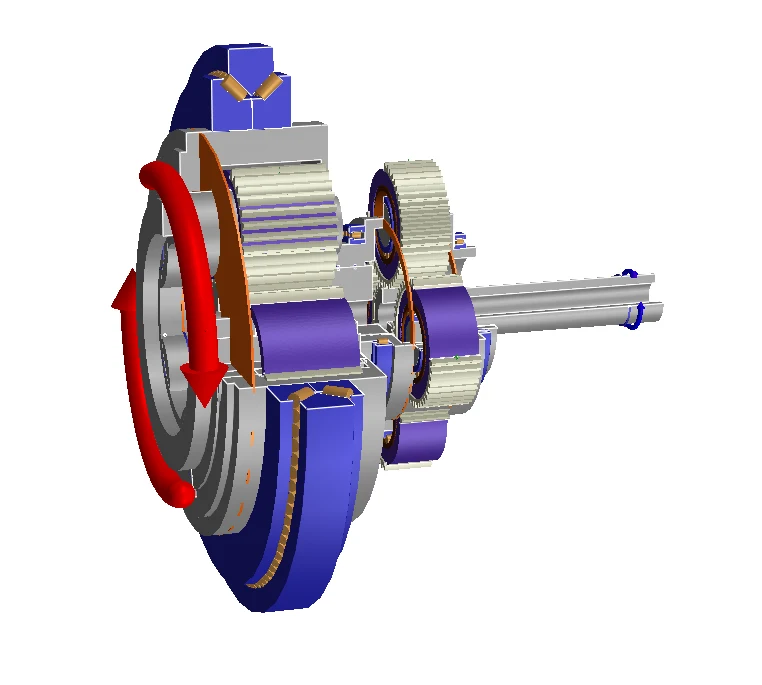
Bearing position
large supports between the main shaft and generator or speed-increasing stage.
Arrangement
semi-direct designs include large-contact-angle double-row or paired single-row tapered rollers; direct-drive examples combine tapered and cylindrical rollers or use paired tapers.
Engineering focus
load paths, shaft stiffness, assembly conditions, temperature rise and cage behaviour.
Application distinction
changes in drive architecture require reassessing load distribution and lubrication rather than reusing another turbine’s life result.
Gearbox: planetary stages and high-speed shafts
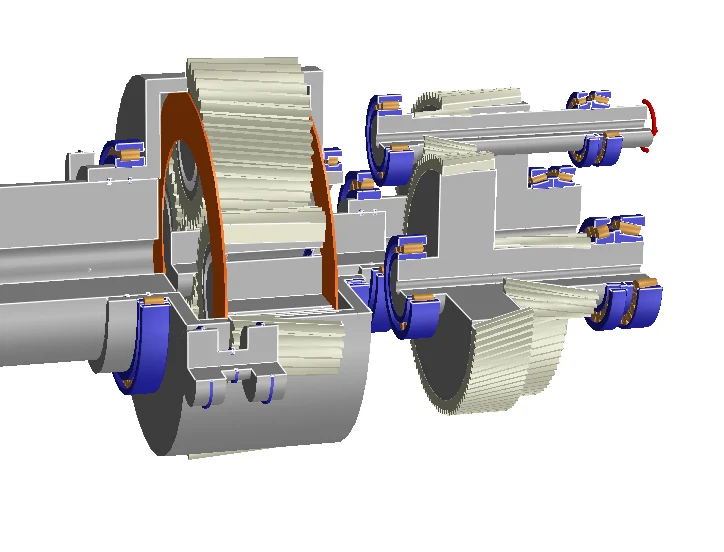
Bearing positions
front/rear planet-carrier supports, planet gears, low- and high-speed shafts.
Conditions
multi-stage load transfer; planet and high-speed supports have different load, speed and space constraints.
Arrangement
tapered carrier supports, outer-ring-free full-complement cylindrical planet bearings, and shaft combinations using cylindrical and paired tapered rollers.
Engineering focus
raceway/roller profiles, cages and surface treatment, contact stress, friction and axial location; supply a load spectrum for the actual stage.
Generator: rotor support and stability
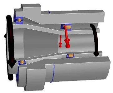
Bearing position
both generator-rotor supports.
Conditions
rotor weight, magnetic forces and speed influence the arrangement; the presentation distinguishes different speed regimes.
Arrangement
paired deep-groove balls, paired tapered rollers, or cylindrical rollers with deep-groove balls, grease lubricated.
Engineering focus
cage/raceway design and lubrication; distinguish electrical damage, fretting and cage failure.
Group example (2025 presentation)
a 6 MW generator using FL-618/500Q1 and FL-NU10/500Q1. Its design targets and running history apply to that installation.
Information for an application enquiry
Equipment and position
machine model, mounting position and complete bearing designation with suffixes. For replacements, include the original arrangement and fit dimensions.
Operating records
bearing speed in rpm, radial and axial loads, shocks and starts/stops. Paper-web and rolling-line speeds are not bearing rotational speeds.
Lubrication and assembly
lubricant grade, oil supply or relubrication records, temperature, mounted clearance or preload, seals and contamination.
Problem and objective
temperature rise, noise, vibration or flaking, timing, photographs and maintenance records, plus the outage window or redesign objective.
Related engineering guides
Clearance, fits and preload in precision equipment →Heavy loads and shocks in casting and rolling mills →Lubrication and temperature in pumps and motors →Replacement assessment for mining and cement equipment →Vibration and noise along gearbox drive trains →APPLICATION SUPPORT
Turn an equipment issue into a technical enquiry
Share the complete designation, position and operating records to discuss arrangements, lubrication, assembly or replacement.
Edited from the group’s 2025 industry presentation · Project records and design targets apply to their specific equipment conditions.
